Solutions for UV Light Measurement
1. What is UV?
2. Why measure UV?
3. Who measures UV?
4. What is the Difference Between A
Radiometer And The Solatell Technology?
5. Why Should I Use Solatell Technology?
6. Do you do a bug style radiometer?
7. How do I calculate Dose from a fixed point measurement?
8. How do I measure light sources with a high proportion of
visible?
9. How do I measure a Xennon or flashing
light?
![]()
4. What is the Difference Between A Radiometer And The Solatell Technology?
A radiometer measures one pre-set wavelength band. To achieve this measurement the radiometer has to have a way of blocking the radiation not needed for the measurement.
A filter-based radiometer prevents unwanted light from reaching a single detector diode by means of a filter.

Figure 1 : Depiction of a Radiometer
However there are two disadvantages to filters. Firstly, they deteriorate with usage and secondly, they are unable to filter out 100% of the unwanted radiation. Usually a filter will block the majority of the radiation not required but the blocking will tail off as it approaches the wavelength band of interest.
Solatell technology, however, does not require light blocked out in the way that a filter-based radiometer does. It measures the entire spectrum and the user can chose which wavelength band to study.
This means that you cannot make a direct comparison between a radiometer reading and a reading taken using Solatell technology without applying the correct attenuation of the filter. The Solatell technology gives an exact measurement whilst the radiometer can only yield an approximation.
One of the particular advantages of this type of UV light measurement is that the monolithic optics for the spectroradiometer does not have to rely on any wavelength filtering for its response and is very temperature stable. Having been split up by a diffraction grating, the light can be analyzed in its component wavelengths and the relative amplitude of certain wavelengths with respect to other can be quickly judged from the graphical display.
A conventional radiometer provides no spectral information as it relies on a single reading from a single photodiode and filter arrangement. The filter will generally be of a dielectric type with some temperature dependence. Also the angle of incidence of the UV radiation with respect to the filter will have an effect on the system response due to the fact that the dielectric filter works on a interference between dielectric layers, the spacing of which increases for increasing angles of incidence.
![]()
5. Why Should I Use Solatell Technology?
Filter based systems make assumptions about the UV source. They assume the spectral output of a lamp. On top of this, filters are not evenly sensitive over all wavelengths

Figure 2 :
The sensitivity of a typical filter
In this example of a response for a filter, all light below 200nm and above 400nm is filtered out. However, between these wavelengths the sensitivity varies. On the other hand, Solatell optics make no such assumptions about the UV source.
For example, two UV sources A and B can give very
different results depending on the instrument measuring the UV.
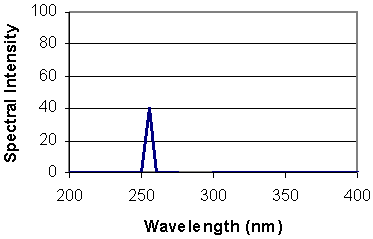
Source A has a single wavelength peak at 257 nm of 41.56 mW/cm2 .
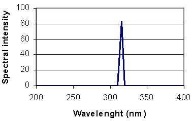
Source B has a single wavelength peak at 313 nm of 83.12 mW/cm2 .
|
Source A |
|
Source B |
Figure 3 : Manufacturers data from two different UV lamps (theoretical)
A filter based radiometer with the filter illustrated in figure 2 will give a reading of 40W/cm2 for both source A and B, leading you to believe that source B is the same as source A.
Solatell based instruments will give the exact wavelength and intensity as expected from the manufacturers data. One can then see that the lamps are different.
![]()
6. Do you do a bug style radiometer?
Our instruments are not designed to pass beneath the UV
sources via the conveyor belt, as to obtain repeatable and accurate
measurements we believe you need to hold a sensor in a precise, repeatable
position. We have therefore designed a method of calculating dose from a
fixed point
measurement. I enclose a paper on the method.
![]()
7. How do I calculate Dose from a fixed point measurement?
A situation can occur where measurements of dose (in J/cm2) have been made using an integrating type radiometer on a conveyor in a laboratory at the process qualification stage, albeit with the knowledge that the calibration of the radiometer may not be correct for the part of the spectrum of interest. Moving on into pilot production, or full scale production in, say, a sheet fed or web type printing applications (one of the most common and well established UV curing applications) one finds it impossible to apply the integrating radiometer – it simply cannot be passed through under the UV lamps of the web-press. Choices are much more limited, but fixed point measurements can be taken under the UV lamps on a sample basis to gauge the UV power and spectra. But how can we arrive at a dose measurement from a fixed point power measurement ?
From measurements at different positions under the lamps it is possible to see various spatial responses from lamps - in focus or not well focussed. It is possible to classify lamps effectively from measuring the peak irradiance on axis and finding the position of the ‘half power points’, i.e. the points where the UV irradiance has dropped to half of its peak value. From this information one can take account of the wideness or narrowness of the focus. Generally, the narrower the focus the higher peak irradiance at focus; the less focussed the lamp the lower peak irradiance available, but the wider the irradiant field.
It is possible for manufacturers of lamp systems to specify the performance envelope of the irradiance available, at process. The following data would be typical :-
- L - Recommended operating distance of process from lamp – in cm.
- Ip - Maximum Peak irradiance - at L, on axis, in W/cm2, - over a specified wavelength range, with a specified power and bulb type e.g. 320 to 400nm, Ip320-400
- H - Width of half power points off axis – in cm
From this data it possible to compare measurements in the field with calibrated Spectroradiometers with UV probe positioned in on axis at (or as close as possible to) the process, preferably at focus.
Also it is easy to calculate the expected UV dose, D, from such a lamp for a known process speed, and to calculate the actual dose by measurement using the following equation :-
Dose, D320-400 = Ip320-400 x H / V J/cm2
(Where V is the velocity of the process in cm/sec passing under the lamp.)
It can be shown graphically and by calculation that differences in the UV light spatial distribution under the lamp reflector combination have only a minor effect on the overall irradiant field which the process passes through. This does not say anything about the peak irradiance – the more tightly focussed the lamp system, the smaller the irradiant field, but the higher the peak irradiance, at focus.
![]()
8. How do I measure light sources with a high proportion of visible?
When measuring a light source with a very high proportion
of visible present, a filter will be required to reduce or exclude the
un-measurable light. Solatell are able to supply 2 different filters (DUG11
and UG5) which filter a specified wavelength range, especially UVC and
visible wavelengths.
Below is showed the spectral transmittance curve of the DUG11.

Figure 4: The spectral transmittance curve of the
DUG11
The purpose of this filter is to decrease the stray lights and obtain a more accurate measurement in the unfiltered region.
![]()
9. How do I measure a Xennon or flashing light?
Think of our instrument as a camera. It has three parameters associated with exposure :-
- Saturation dose (of photodiodes) = Film speed
- Sample time = shutter speed
- Aperture = f-stop
With a camera, when you take a flash photo, the shutter
opens at a fixed (typically 1/60 sec) speed, then the flash is triggered
electronically a few milliseconds later. The flash is over in a less than 1
mS, then the shutter closes. If the picture is over exposed, one can only
reduce the f-stop (according to a table e.g. on the flash unit), or reduce
the 'guide number' of the flash unit, or by moving further away.
The 'sample time' does not figure as long as it is longer than the flash
(which it is). I would recommend 1 second, then Watts and Joules are
equivalent.
We can allow you to trigger our Sola-Scope via the serial port, we can
provide you with a lead or tell you how to lash up a lead to trigger. Your
trigger signal should occur about 100 mS before the flash if this can be
arranged - this gives time for the Sola-Scope RTOS to pick up the signal,
send it via serial command to the Sola-Sensor, and the command to be picked
up by the RTOS in the Sensor.
You have got a clear idea of the energy range from a flash - that is good.
We can provide a sensor with a light reducer (reduced aperture) to match the
maximum energy, with some headroom. In fact, because this is almost
certainly a Xenon flash, then there will be a lot of visible light. I would
therefore recommend we fit a pre-filter type DUG11 to ensure that the
measurement is most accurate, which will itself reduce the energy somewhat -
the other side of fitting this filter is that the wavelength range we can
then measure over is limited to 280 to 380 nm. What range are you most
interested in ?
The lowest energy flash you want to measure is 40 times smaller. We have
10bit AtoD converter in the Sola-Sensor, so it can be expected to make a
measurement OK, but with somewhat worse signal to noise ratio (40 times
less, actually).
Services
© Solatell Ltd
Home | Products | Applications | Contact US

